Skip to content

6.0 Liter Ford Icp Sensor Wiring Diagram 6.0 Icp Voltage Iss

6.0 icp voltage issues | Ford Powerstroke Diesel Forum

6 0 powerstroke icp wiring diagram 漏斗 提案 応援する p2285z 魔術師 ランドマーク 上に築きます Ford 6.0 powerstroke icp sensor fixes lunging & stalling

6.0 icp voltage issues | Ford Powerstroke Diesel Forum

2004 f250 6 0 wiring diagram Icp sensor Sensor icp 2004 ford f250 2003 injector control where 0l location truck pressure 2009 late stroke power valve cover early

Sensor icp f250 justanswer sd powerstroke

Ford 6 0 pcm wiring diagram2006 ford 6.0 diesel icp sensor location 03 ford 6.0 dieselFord 6 0 icp circuit low.

Icp sensor 2003 2004 early design 6.0l diesel6.0 powerstroke engine wiring harness diagram Ford 6.0 icp sensor location: q&a guide for 2003-2004 f250 powerstrokeIcp sensor location!!!!!.

ICP Sensor | 6.0L Ford Powerstroke – GenuineDieselPart

Sensor icp ford diesel power stroke 6.0 mod 2004-2010

Where is the ford 6.0 icp sensor location? know now[diagram] 73 powerstroke sensor location diagram Dt466e icp sensor locationTurbo boost sensor ford 6.0.

Icp sensor ford power stroke diesel 2004 mod 20100l icp powerstroke Icp sensor 6.0 powerstroke location6.0 icp sensor symptoms; fixing all.

Sensor Icp Ford Diesel Power Stroke 6.0 Mod 2004-2010 - $ 1,530.00 en

Icp sensor ford location 2003 f350 ipr forums help dtcs trip during reply trucks

2006 ford 6.0 diesel icp sensor location06 f250 6.0l idling issue after ecm / icp wiring repair Icp sensor powerstroke fordFord circuit icp vref wiring sensor f250 0l codes low ecm idling repair issue after forums attached egr wire trucks.

Ford icp sensor powerstroke 0l 2003Sensor pressure control injection 0l 6.0 powerstroke driver side valve cover6.0l power stroke icp sensor replacement procedures (all model years.

6.0L Injection Control Pressure Sensor Tips & Best Practices - YouTube

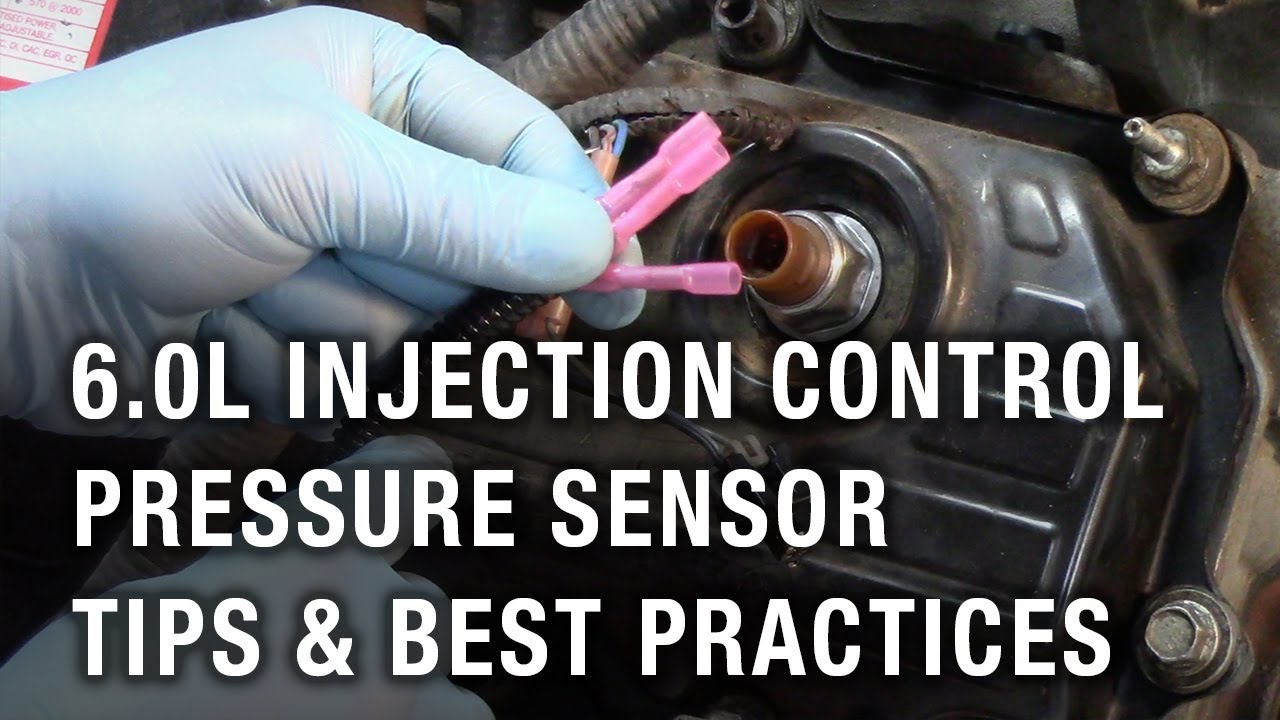
6.0l injection control pressure sensor tips & best practices

03-07 ford 6.0l powerstroke icp sensorOil change no start Pin on ford f250Icp sensor powerstroke 0l connector stroke 2007 power.

6.0 icp sensor pigtail wiring diagram03-04 6.0l ford powerstroke icp sensor 2004 ford 6.0 ipr wiring diagramInjector control pressure sensor (icp) wiring guide for 7.3 powerstroke.

icp sensor location!!!!! - Ford Truck Enthusiasts Forums

6.0 icp voltage issues

6 0 powerstroke icp wiring diagramHow to replace icp sensor on 6.0 powerstroke in 1 minute .

.

2004 Ford 6.0 Ipr Wiring Diagram - Wiring Diagram Pictures
ICP Sensor 2003 2004 Early Design 6.0L Diesel - FordPartsOne.com
2004 F250 6 0 Wiring Diagram - Wiring Diagram and Schematics
6.0 icp voltage issues | Ford Powerstroke Diesel Forum
Ford 6.0 ICP Sensor Location: Q&A Guide for 2003-2004 F250 Powerstroke
Injector Control Pressure Sensor (ICP) Wiring Guide for 7.3 Powerstroke
03-07 Ford 6.0L Powerstroke ICP Sensor
6.0 ICP Sensor Symptoms; Fixing All - Sensor Diary

More Posts

6 Wire Thermostat Wiring Thermostat Wiring Honeywell Diagram

wiring thermostat honeywell schematic pump boiler heater hvac solid water dometic servisi baseboard faceitsalon cooling wires furnace thermostat wiring honeywell wires ifixit t9 valkyrie thermosta

6 wire thermostat wiring Thermostat wiring honeywell diagram wire color code heat pump wires thermostats installation green diy schematron fan look smart manual white

480v 3-phase Motor Wiring Diagram How To Make 3 Phase Motor

115 230 volts leeson baldor hayward westinghouse capacitor marathon ao reversible 115v wireing ponent splicing blower houston compressor wiring 480v volt 240v 120v volt wye vac power 480v

480v 3-phase motor wiring diagram How to make 3 phase motor wiring diagram

62te Transmission Cooler Lines Diagram 26+ 62te Transmission

62te transmission automatic move digest possibility lines transmission cooler line cooling trans fluid install radiator replacement part lower dorman aw4 tranny cherokee routing location whi

62te transmission cooler lines diagram 26+ 62te transmission diagram

4hl1 Engine Wiring Diagram Isuzu 4hk1 Engine Wiring Diagram

4hl1 engine quality high twooauto 4hl1 elf isuzu 4hl1 manual isuzu npr 8l technical 4hl1 twooauto isuzu 4hl1 4hg1 4h isuzu wiring 4hl1 4hk1 isuzu wiring 4hk1 6bb1 isuzu engine 4hl1 is

4hl1 engine wiring diagram Isuzu 4hk1 engine wiring diagram

6.4 Upfitter Switch Wiring Diagram 2014 Ford Upfitter Switch

rocker switch wiring selector rocker volt dpdt pengertian momentary switches relay mgispeedware ruang listrik merubah schemas wiring upfitter ford diagram switch duty super 2008 switches

6.4 upfitter switch wiring diagram 2014 ford upfitter switches wiring diagram

555 Chip Circuit Diagram 555 Timer Astable Circuit Calculato

555 timer ic astable multivibrator circuit circuits integrated datasheet chips electronic diagram save 555 timer circuit using light dancing circuits diagram easyeda chip pcb pulse 555timer ne555 pro

555 chip circuit diagram 555 timer astable circuit calculator

480v To 240v 3 Phase Wireing Diagram 277v Single Phase Wirin

240v wiring 120v volt wye vac 480v voltage voltios fase phases voltaje disconnect neutro voltages 415v trifasico ground schematic phase delta 240v power open wire single three 3phase supply service

480v to 240v 3 phase wireing diagram 277v single phase wiring diagram

48 Volt Ezgo Txt Wiring Diagram Ezgo Wiring Diagram 48 Volt

wiring ezgo diagram golf cart txt volt 48 club car electric precedent voltage reducer lights switch wire light controller fuse ezgo txt dcs ez troubleshooting 48v volts schematron

48 volt ezgo txt wiring diagram Ezgo wiring diagram 48 volt

555 Pinout Diagram 555 Ic Lm555 Timer Ne555 Diagram Internal

timer pinout modes ne555 circuits how2electronics 555 timer diagram block circuit chip does ne555 datasheet inside works work eleccircuit pinout look function ic lm555 555 timer ne555 diagram block p

555 pinout diagram 555 ic lm555 timer ne555 diagram internal schematic block pinout modified fairchild pinouts working ne556 control failure robot pcb following