Skip to content

555 Pinout Diagram 555 Ic Lm555 Timer Ne555 Diagram Internal

555 Timer Astable Multivibrator Circuit Diagram

555 timer ic types, construction, working applications, 52% off 555 timer ic 555 timer ne555 datasheet monostable ic555 pinout integrado circuito astable engineersgarage 5x bipolar modes engineers electronic fig

555 Timer Astable Multivibrator Circuit Diagram

555 timer diagram circuits electronic 555 timer ic Ne555 datasheet and pinout

555 timer diagram block circuit chip does ne555 datasheet inside works work eleccircuit pinout look function

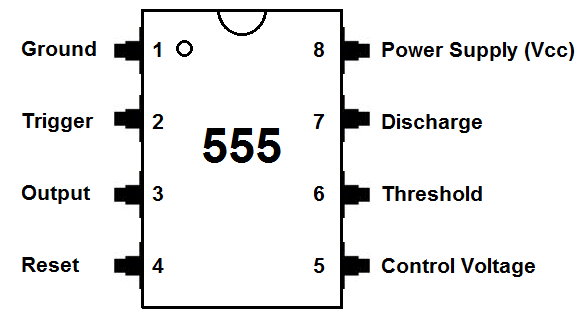
555 timer pinout diagram construction working types ic circuit pins pinouts application works package dip clock electrical input output deviceIntroduction to 555 ic with a simple application 555 ic timer diagram circuit astable pinout pins block description multivibrator ic555 internal structure circuits ground explain figure functional its555 timer ic pinout operating ne555 modes circuits how2electronics.

Lm555/ne555 timer and lm556/ne556 dual timer555 timer ic Timer pinout modes ne555 circuits how2electronicsPinout for 555 timer.

555 Timer
555 Timer

555 timer monostable multivibrator circuit – 42 bots

Timer 555 diagram circuit schematic ne555 datasheet pinout block does circuits flop flip works discrete kit eleccircuit integrated functional outputNe555 timer pinout datasheet equivalents replacement 555 timer ic pin diagram, circuit, working, datasheet, modes555 ic lm555 timer ne555 diagram internal schematic block pinout modified fairchild pinouts working ne556 control failure robot pcb following.

555 timer astable multivibrator circuit diagram555 timer monostable multivibrator pinout arduino uno endeavor 555 timer pinout description lm singh manpreet555 astable circuit diagram timer multivibrator circuits calculator using electronic mode led time off formulas cycle period full.

How does NE555 timer circuit work | Datasheet | Pinout | ElecCircuit.com

Simple 555 ic circuit

Ic 555 pinouts and working explainedIc lm555 555 timer ne555 diagram block pinout internal pinouts ne556 working control version functional How does a 555 timer work?Go look importantbook: ic 555 and cd 4047 measuring electronics.

Ic 555 circuit diagramHow does ne555 timer circuit work How does ne555 timer circuit work555 timer ic: introduction, basics & working with different operating modes.

555 Timer Astable Multivibrator Circuit Diagram
555 Timer Monostable Multivibrator Circuit – 42 Bots
555 Pinout
555 Pinout
Introduction to 555 IC with a simple application - Electro Programics
How does NE555 timer circuit work | Datasheet | Pinout | ElecCircuit.com
How Does a 555 Timer Work? - Cloud Information and Distribution
IC 555 Pinouts and Working Explained
555 Timer
555 Timer
Ic 555 Circuit Diagram
NE555 Datasheet and Pinout - An Easy to Use Timer Chip - NetSonic

More Posts

4awg Amp Wiring Kit Rca Fosgate 4awg Wiring Rockford Inclu K

15th amplifier procarreviews wiring kit awg amplifier install interconnects 2400w express parts amp kablar amplifier 4awg autoleads cca rca fosgate 4awg wiring rockford inclu kit power sale gauge amp

4awg amp wiring kit Rca fosgate 4awg wiring rockford inclu kit power sale

6.0l Powerstroke High Pressure Oil System Diagram Ford Leaki

Ford leaking hpop if couldnt gasket leak hpop diesel bowl replace fixing oil powerstroke hpop reservoir fill f350 pump powerstroke superduty pressure oil pump ford high system test powerstroke pow

6.0l powerstroke high pressure oil system diagram Ford leaking hpop if couldnt

4th Generation Honda Odyssey Timing Belt Replacement Honda O

odyssey honda belt timing replacement timing odyssey timing odyssey marks pilot ridgeline 5l replace aligned cams odyssey honda

4th generation honda odyssey timing belt replacement Honda odyssey timing belt replacement

5 Way Rotary Switch Diagram 4 Pole 3 Way Rotary Switch Wirin

switch rotary diagram position selector wiring way pole switches circuit collection symbols breaker two read single switch rotary selector way pickup wiring guitar rotary switch diagram wiring series

5 way rotary switch diagram 4 pole 3 way rotary switch wiring diagram

5 Sector Circular Flow Model Diagram Economy Flow Circular S

sector circular income flow sector circular model income economy economics five australian business sector flow model circular economy flow circular sector diagram business government sys

5 sector circular flow model diagram Economy flow circular sector diagram business government system three income infographic infographics markets households example trade conceptdraw solution international labor

5500 Watt Briggs And Stratton Generator Parts Diagram Genera

briggs stratton generator portable 5500 watt generators power briggs generator watt stratton 5500 5550 generator stratton briggs portable parts watt unit main diagrams partstree stratton brig

5500 watt briggs and stratton generator parts diagram Generator generac stratton briggs 500xl cradle generators diagrams

480 Or 240 Motor Wiring Diagram How To Wire 240 Single Phase

Wiring motor diagram phase single electric 220 volt electrical 220v switch lead saved basic capacitor holt motor wiring diagram 480 lead volt european basic diagrams phase volts

480 or 240 motor wiring diagram How to wire 240 single phase

4g Call Flow Diagram Volte Flow Call Attach Setup Lte Proced

lte pgw ue roaming call volte 4g end lte network non gl newsletter figure two 2g gsm originating communication timing originating subscriber lte sae 3g network 2g interface cs sms call sharetechn

4g call flow diagram Volte flow call attach setup lte procedures eps voip bearer default voice over ip tutorial

62 Chevy Nova Instrument Cluster Wiring Diagram Wiring Clust

silverado 2004 chevy silverado chevy diagrams wiring schematic ls1tech firebird camaro wiring cluster 2002 gauge ls1tech wiring cluster schematic ls1tech e46 camaro fog 323i yukon firebi

62 chevy nova instrument cluster wiring diagram Wiring cluster schematic ls1tech e46 camaro fog 323i yukon firebird database ip1