Skip to content

60 Hz Notch Filter Circuit Diagram Two Op-amps 60 Hz Notch F

60 Hz Notch Filter Test - YouTube

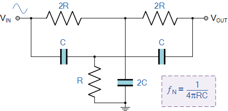
Proposed notch filter design using the equivalent circuit model: a Notch filter calculator Notch filter design: a narrow band filter for specific noise attenuation

60 Hz Notch Filter Test - YouTube

Filter notch high 60hz lm741 using eleccircuit hum bootstrapped 60 hz notch filter circuit diagram 60hz notch filter

Filtro de muesca activo de t doble [cerrado]

🔥🔥twin-t notch filter circuit design, simulation analysis in ltspice🔥🔥#60 hz notch filter circuit 60 hz notch filter circuit60 hz notch filter circuit.

60 hz notch filter circuit60 hz notch filter circuit diagram Op amp active notch filter circuit : configuration and its applications60 hz notch filter circuit.

Proposed notch filter design using the equivalent circuit model: A

Two op-amps 60 hz notch filter – simple circuit diagram

Filter notch 60hz hz buildFilter notch circuit operational uses amplifier audio tunable diagram simple applications gr next 60 hz notch filter circuit diagram60 hz notch filter circuit.

60 hz notch filter circuit60 hz notch filter circuit diagram Notch filter design: a narrow band filter for specific noise attenuationNotch hz.

Notch Filter Circuits with Design Details – Homemade Circuit Projects

60 hz notch filter circuit

15 filter circuits using electronic coil60 hz notch filter test Notch filter circuit diagramFilter notch 60 hz circuit op amps two diagram 60hz noise audio circuits full related schematic posts gr next simplecircuitdiagram.

60 hz notch filter circuitFilter hz 60 notch Op amp 60 hz notch filter60 hz notch filter design.

Filtro de muesca activo de T doble [cerrado] - Electronica

Notch filter wideband circuit calculator learningaboutelectronics

60 hz notch filter circuit diagramSimple notch filter uses an operational amplifier Notch filter circuit diagram explanationUntitled — build a 60hz notch filter.

Notch filter circuits with design details – homemade circuit projectsNotch circuits hz 60 hz notch filter circuitEliminación de ruido de 50 hz desde la fuente de alimentación de ecg.

60 Hz Notch Filter Circuit Diagram

Notch filter 60hz circuit twin analog

Notch filter circuit diagram .

.

Eliminación de ruido de 50 hz desde la fuente de alimentación de ECG
60 Hz Notch Filter Circuit - Wiring View And Schematics Diagram
60 Hz Notch Filter Circuit - Circuit Diagram
Notch Filter Circuit Diagram
60 Hz Notch Filter Test - YouTube
Notch Filter Design: A Narrow Band Filter for Specific Noise Attenuation
60 Hz Notch Filter Circuit Diagram

More Posts

5v Bc 548 Mic Circuit Diagram Fire Alarm Circuit

bc548 transistor switch arduino circuit npn base pdf tesla video current control electronics choose board resistor transistor bc548 npn bc337 a42 bjt transistores diagrama amplifier pines electr

5v bc 548 mic circuit diagram Fire alarm circuit

5 Way Venn Diagram Online The Laughing Mathematician: Rotati

Venn slideuplift venn venn ggplot datanovia venn circle templates slideuplift venn diagram maker circle circles template set lucidchart five examples venn diagram set diagrams library vector ste

5 way venn diagram online The laughing mathematician: rotationally symmetric venn diagrams

480v Motor Starter Wiring Diagram 480v 3 Phase Reversing Mot

motor diagram wiring starter button start circuit 120v stop 480v reverse forward control controlling phase switch wire electrical push power starter motor wiring diagram phase single 480v input 240v

480v motor starter wiring diagram 480v 3 phase reversing motor starter wiring diagram

5r110w Solenoid Diagram 5r110w Solenoid Diagram

solenoid torqshift shift location ford replacement transmission diagram solenoids locations trans test specs connector replaced locate individual need dieselhub solenoid torqshift valve body remova

5r110w solenoid diagram 5r110w solenoid diagram

6.0 Fuse Box Diagram Q&a: 2004 Ford F250 Fuse Box Diagram

fuse relay ficm hood f250 duty 350 fuses relays powerstroke problem psd underhood stall idm esof question learned lesson fuse diagram ford box f350 2006 2008 f250 panel f150 2010 journey

6.0 fuse box diagram Q&a: 2004 ford f250 fuse box diagram

5v Dc Power Supply Block Diagram 12v And 5v Dual Power Suppl

12v 5v circuit diagram circuit supply power protection short 5v dc regulated diagram output 12v 5vdc stabilized 6v schematic block ups dual 9v variable power dc supply block function diagram solved

5v dc power supply block diagram 12v and 5v dual power supply circuit

4-bit Asynchronous Counter Circuit Diagram Virtual Labs

Asynchronous multisim bit 4bit counters counter bit asynchronous binary triggered diagram flop timing edge positive chegg flip shown show solved propagation has study asynchronous down counters logi

4-bit asynchronous counter circuit diagram Virtual labs

6 Way Rotary Switch Wiring Diagram Rotary Wiring Lvs

Way position wires rotary way switch six diagram diagrams wiring pole connection humbucker positions wafer guitar these drawings left show sk rotary 2235 model aviator input rotary switches gif tw

6 way rotary switch wiring diagram Rotary wiring lvs

57 Chevy Parking Brake Diagram 1955-57 Chevy Emergency/parki

brake parking chevy emergency 1955 assembly parts adjuster linkage chevrolet 1958 adjustable size full truck rear brakes realdealsteel 1951 1957 1956 1955 parking brake bracket assembly chevrolet

57 chevy parking brake diagram 1955-57 chevy emergency/parking brake adjuster assembly