5000 Watt Pure Sine Wave Inverter Circuit Diagram Make This
1kva (1000 watts) pure sine wave inverter circuit using 555 ic 5kva ferrite core inverter circuit Inverter ac circuit diagram
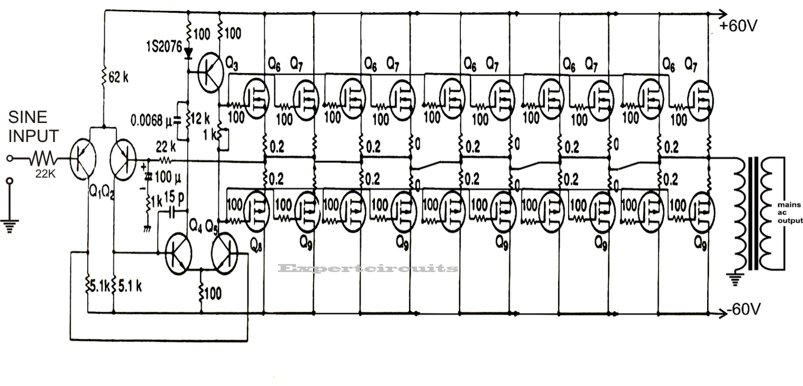
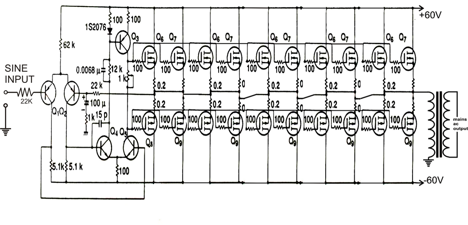
Designing 1kW Sine Wave Inverter Circuit | PCB Design Full Guide
Inverter circuit diagram 5000w / 250 to 5000 watts pwm dc ac 220v power Pure sine wave inverter design 300 watts pwm controlled pure sine wave inverter circuit – homemade
Build a 300w/800va pure sine wave inverter
Simple pure sine wave inverter circuitInverter circuit sine wave diagram board schematic solar power projects electronics arduino full inverters 1000w using diy ic charger 50hz [diagram] 1000 watts inverter using transformer diagramsInverter sine wave pure circuit diagram pwm watt simple watts controlled 1000 circuits output true sinewave voltage power mikrora diy.
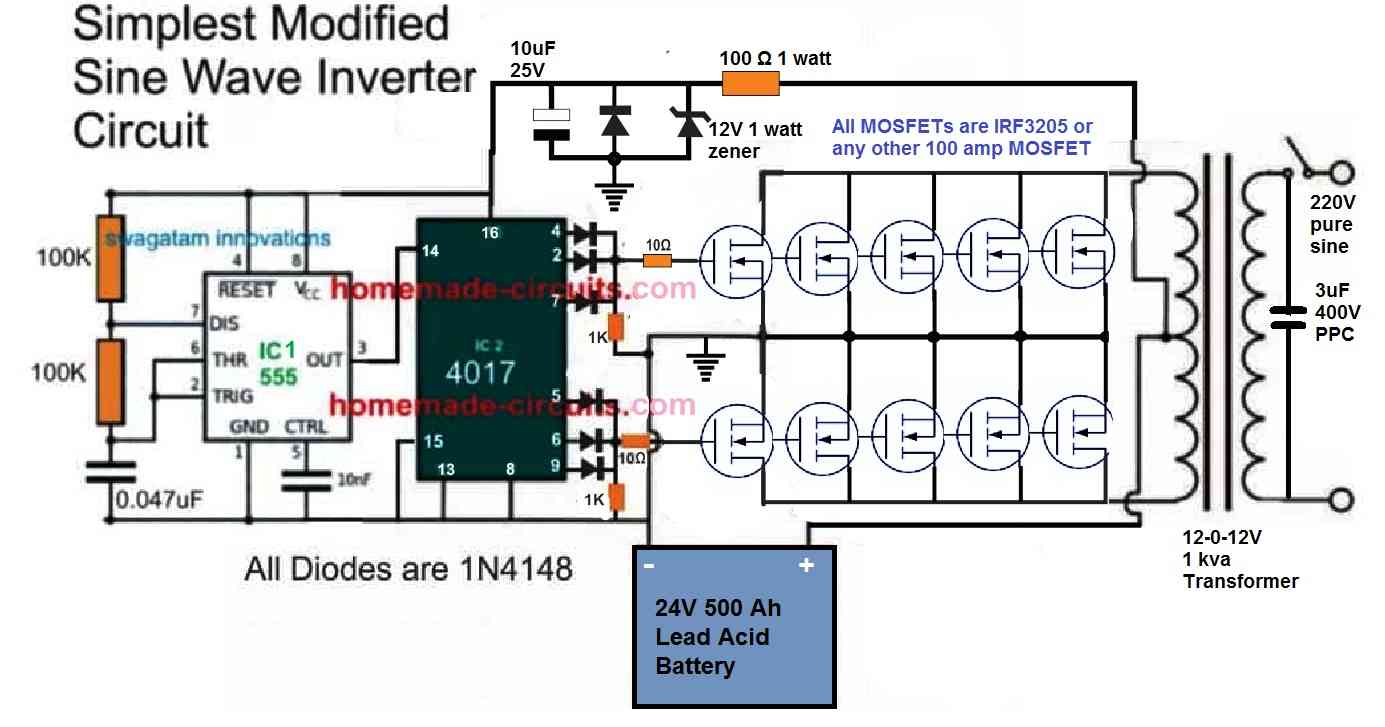
Inverter circuit sine wave pure pwm homemade make diagram output ic 555 circuits using correction watts stage power generator voltagePure sine wave inverter, using ic 555 Make this 1kva (1000 watts) pure sine wave inverter circuit – homemadeInverter 5000w watt ferrite 5kva circuits 220v homemade calculation core diy schematics pcb.

555 ic circuit wave sine inverter pure circuits diagram homemade using pwm generator square electronic build triangle simple stage
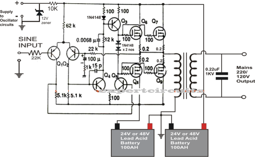
Pure sine wave inverter circuit diagram pcbSine circuit wave inverter generator pure simple using amplifier diagram power watt homemade sinewave output true ac input ic opamp 300 watts pwm controlled, pure sine wave inverter circuit with outputInverter circuit 5000w 220v pwm 50hz watts oscillator.
Schematic inverter pure sine waveDesigning 1kw sine wave inverter circuit 220vdc to 220vac inverter circuit diagramSimple pure sine wave inverter circuit.
5000w pure sine wave inverter circuit diagram
1kva (1000 watts) pure sine wave inverter circuit using 555 ic5000w inverter circuit diagram pdf home wiring diagram Inverter sine wave circuit pure simple diagram wiring battery watt inverters power homemade circuits electronic modified above detailsInverter sine 1kva watts 5000w generator hz watt digital world1 elect circuits installation schematics stepped waveform kva complete oscillator 1kv.
Circuit inverter sine wave pure diagram schematic watt 1000 1kva 2000w 12v parallel simple watts make using amplifier transistors circuits .


![[DIAGRAM] 1000 Watts Inverter Using Transformer Diagrams - MYDIAGRAM.ONLINE](https://2.bp.blogspot.com/-BqXTr9re-o0/TbPMIjq_AOI/AAAAAAAAAUk/6VQvIaxtA8Y/s1600/Inverter+PWM+5000W.png)