5 2 Solenoid Valve Diagram Valve Solenoid Pneumatic Valves U
How solenoid valves work Gas solenoid valve wiring diagram Solenoid valve working principle
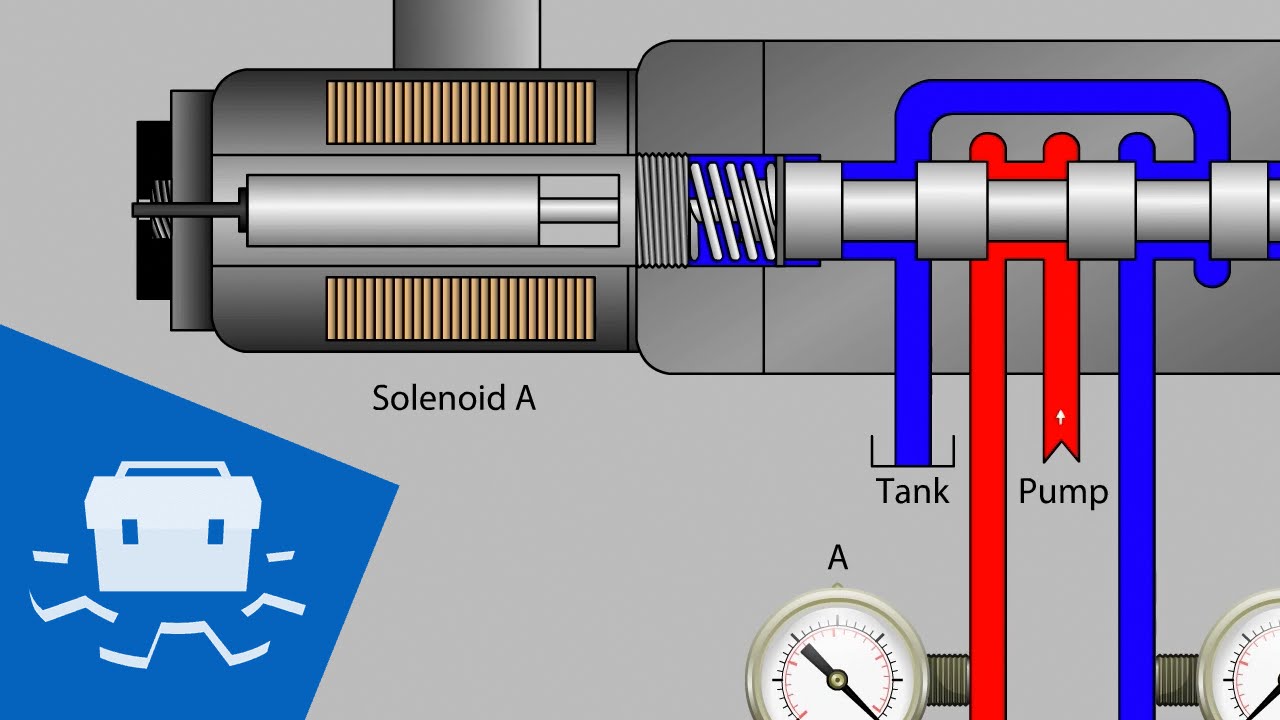
[DIAGRAM] F150 Solenoid Diagram - MYDIAGRAM.ONLINE
Pneumatic solenoid valve operation valve solenoid basics know related 5 3 solenoid valve circuit diagram 3 way port 2 position 12v 24v 220v pneumatic air solenoid valve
Pneumatic solenoid valve wiring diagram
Sy7120-5yo-02f-q: solenoid valve 5Smc 5/2 pneumatic solenoid valve Valve solenoid pneumatic valves uflow operated 24v spool port directionalValve solenoid solenoids hvac diagram control thanks.
Solenoid pneumatic 220v 24v 6mm volt 8mmSolenoid feed override pneumatik hafner bistable Hvac solenoids – hvac troubleshooting5/3-solenoid-valve, centre closed, g 1/2".

[diagram] f150 solenoid diagram
Solenoid valves work they5 2 way valve symbol 5/2 double solenoid valve manufacturers and suppliers in india andSolenoid configuration.
Solenoid valve valves actuator principle coil cooling5/2 solenoid valve v51b511a-a2000 Hydraulic solenoid valve wiring diagram[diagram] 4t65e solenoids diagram.

What is the function of solenoid valve solenoid principle
How to apply safety edge (pressure sensitive) devices24vdc solenoid pneumatic valve Valve solenoid pneumatic 24vdc 24v cytronPneumatic solenoid valve: what is it? how does it work?.
Pneumatic control solenoid valveExploring the industrial applications of solenoid valves Electro-pneumatic simulation of circuit of vcv with 5/2 solenoid valveSolenoid valve symbol schematic valve symbols solenoid schematic.

Solenoid gas valves
Solenoid valves: how they workSolenoid valve 24vdc coil aro 24vdc solenoid valve coil; 22mm; din 43650b 5/2 single solenoid valve with spring return manufacturers and5/2 way pneumatic solenoid valve for double acting cylinder.
The configuration of solenoid valve.5/2 way single solenoid valves Pneumatic solenoid valve working principle solenoid valve animationSy51205lou01fq: solenoid valve 5.
Solenoid valves
Valve schematic pneumatic symbols read block spring solenoid symbol apply edge safety blocked part oid solen down welcomeSolenoid valve symbols explained .
.


![[DIAGRAM] F150 Solenoid Diagram - MYDIAGRAM.ONLINE](https://i2.wp.com/instrumentationtools.com/wp-content/uploads/2016/12/instrumentationtools.com_four-way-solenoid-valve-diagram.jpg)


