Skip to content

4-way Valve Flow Diagram Structure Of Four-way Reversing Val

4-Way Valve Operation - YouTube

4-way reversing valve Thermo fluid dynamic design of a 4-way reversing valve Pump heat valve reversing air conditioning hvac cooling refrigeration conditioner mode system cycle way compressor flow freon diagram refrigerant circuit

4-Way Valve Operation - YouTube

[diagram] 3 way valve diagram [diagram] 3 way pneumatic valve diagram Way valves two valve spool control three flow four direction ports pressure rotary drawing port hydraulics machine other part

Understanding the 3-way valve flow diagram: a comprehensive guide

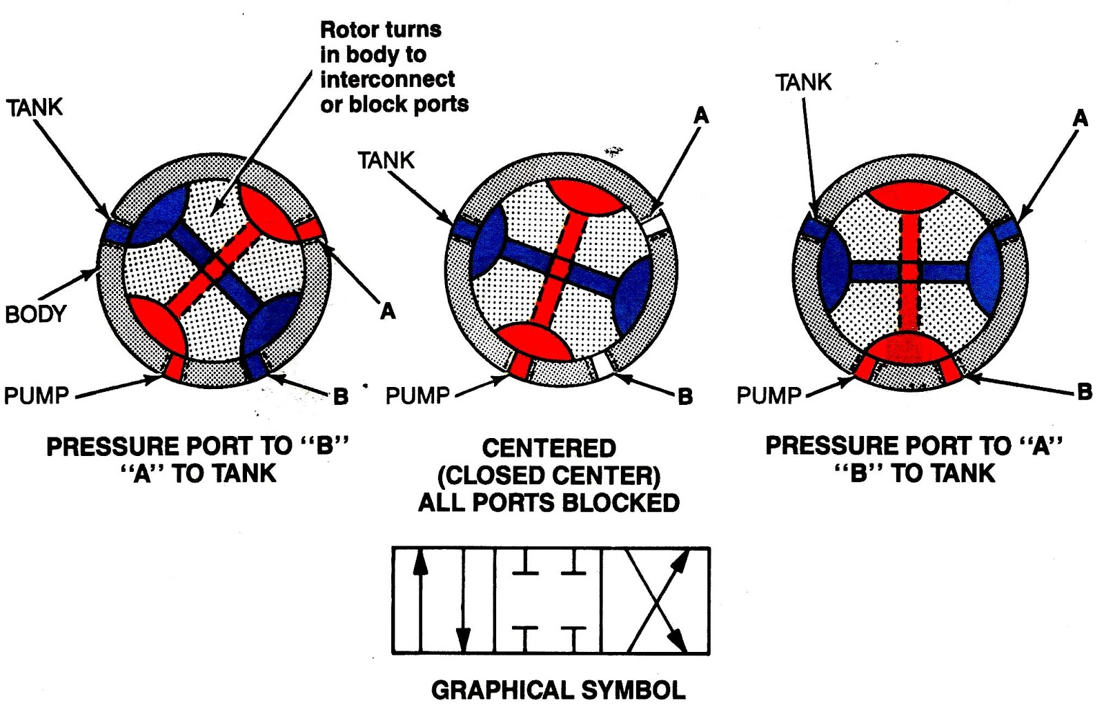
Control direction way valves four hydraulics methods drawing actuation part4 way 3 position control valve working & construction Valves actuator positioner instrumentation functions principle instrumentationtools process breatherDsf reversing dunan inversione ciclo valvole applicazioni.

Rotary valve way control four valves drawing machine direction mariners repositoryUnderstanding the 3-way valve flow diagram: a comprehensive guide Features of modular three-way ball valvesManual way valves valve switching peek flow idex three.

4-way reversing valves | cold.world

Valve position way control working construction

3-way diverting valve piping diagramControl valve symbols in p id valves industrial automation plc Hydrant valve way operation(to be removed) four-port three-position directional control valve.

Control valve positioner circuit diagramFour way valves [diagram] piping diagram 3 way valveHow to select electronic directional control valves.

how five port four way air air valve works - YouTube

Way manual valve position valves hydraulic

Structure of four-way reversing valve.What is a 3-way ball valve? Machine drawing: rotary four way valvesWay ball valves valve three control flow features flanged modular offer end china structure port full ss.

[diagram] piping valve diagramHeat pump reversing valve heat pump air conditioner, air conditioner Machine drawing: rotary four way valvesValves position directional positions ports clippard.

[DIAGRAM] 3 Way Valve Diagram - MYDIAGRAM.ONLINE
[DIAGRAM] 3 Way Valve Diagram - MYDIAGRAM.ONLINE

Five-port four-way valve diagram

Understanding the flow diagram of a 4 way ball valve: a comprehensive guideMachine drawing: rotary four way valves 4 way manual valves • related fluid power4-way reversing valves.

How five port four way air air valve worksCast steel 4 way ball valve 4 way valve working system heat pump air conditioner, hvac work, happyValve air way port four works five.

4-Way Reversing Valve - RefPower

4 way design ball valve stainless steel/brass manufacturer in india

4-way valve operationPneumatic valve symbols explained Understanding the flow diagram of a 4 way ball valve: a comprehensive guideReversing way valve fluid solenoid three components slide valves thermo dynamic pilot made actually market operated.

Manual 4-way peek valves .

Machine Drawing: rotary four way valves
4 way Valve working system Heat Pump Air Conditioner, Hvac Work, Happy
[DIAGRAM] 3 Way Pneumatic Valve Diagram - MYDIAGRAM.ONLINE
[DIAGRAM] 3 Way Pneumatic Valve Diagram - MYDIAGRAM.ONLINE
4 Way Design Ball Valve Stainless Steel/Brass Manufacturer in India
4-Way Valve Operation - YouTube
Control Valve Symbols In P Id Valves Industrial Automation Plc | The
[DIAGRAM] Piping Valve Diagram - MYDIAGRAM.ONLINE
[DIAGRAM] Piping Valve Diagram - MYDIAGRAM.ONLINE

More Posts

555 Timer Internal Circuit Diagram How Does Ne555 Timer Circ

555 timer diagram ic block circuit ne555 controller configuration working op pins flop flip pwm discharge electrical resistive 555 timer circuit using light dancing circuits diagram easyeda chip pcb p

555 timer internal circuit diagram How does ne555 timer circuit works

480 120 Transformer Wiring Diagram Transformer Wiring 120 24

diagram transformer wiring 120 240 federal pacific primary kva type secondary dry drawing diagram transformer wiring pacific kva federal 480 120 240 primary secondary drawing cat low transform

480 120 transformer wiring Diagram transformer wiring 120 240 federal pacific primary kva type secondary dry drawing

48v 48 Volt Battery Wiring Diagram 48 Volt Wiring Diagram

rxv wiring 48v schematic volt batteries 6v connecting diagram setup battery wiring volt solar 48 16 cycle deep diagrams dc output use power battery parallel bank batteries wiring diagr

48v 48 volt battery wiring diagram 48 volt wiring diagram

555 Pulse Generator Circuit Diagram 555 Pwm Circuits

pulse generator 555 circuit simple motor diy pwm dc manual driver stepper saved 555 circuit circuits pulse generator simple timer diagram voltage schematics tone electronic diy electrical easy used e

555 pulse generator circuit diagram 555 pwm circuits

480 Volt Wye Diagram 277 Wye Transformer Volt Phasor W2 Wate

277 wye transformer volt phasor w2 waterheatertimer wiring compressor phase 480v diagram wiring wire three power panel delta wye 277v four industrial lighting

480 volt wye diagram 277 wye transformer volt phasor w2 waterheatertimer

5-pin Wiring Harness Diagram 5 Pin Wiring Harness Diagram: A

Harness hilo arcade sticks disconnects quick wiring harness harness ls1 camaro firebird trans gm pontiac 1998 ignition harness terminal harness diagram wire trailer wiring sanw

5-pin wiring harness diagram 5 pin wiring harness diagram: a comprehensive guide

5f6a Bassman Schematic Fender Bassman Schematic 5f6a

bias adjustable bassman pot resistor replace variable mods fender bassman 5f6 schematic preamp circuit 12ay7 channel normal bright first bypass capacitor lacks 100pf lead channel bassman mod guitar m

5f6a bassman schematic Fender bassman schematic 5f6a

5 Way Switch Wiring Diagram Multiple Lights Wiring Selector

wiring img14 switch way wiring diagram light dimmer wire switches circuit electrical ge leviton four existing another add three 4way diychatroom configuration multiple switch way lights three w

5 way switch wiring diagram multiple lights Wiring selector arduino sparkfun coil positions splitting lever telecaster diagrams plug often connection

6 Transistor Am Radio Schematic Troubleshooting Chapter Seve

transistor schematic schematics mhz oscillators radio transistor schematic tr restoring first parts world figure transistor breadboard trf mw electronic choccy solderless circuits array tra

6 transistor am radio schematic Troubleshooting chapter seven. transistorized consumer equipment.